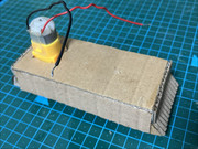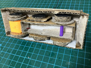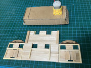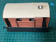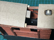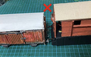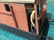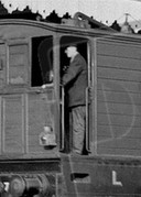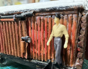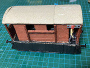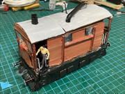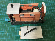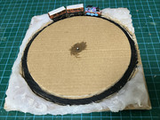
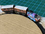
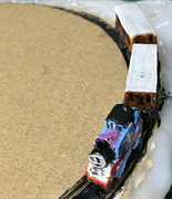
To practice building and detailing a micro train “layout” like this with objects and scenery - and in honour of this year’s upcoming Thomas reboot - I made a full base with new versions of Thomas, Annie and Clarabel (that don’t represent Plarail) and themed it after the first intro of the original series. Hot melt glue was used to form “terrain” on the corners and make them closer in height to the middle, making sure it didn’t stick to the “track” disc and to leave a gap in one side (since there are no gears or a crank to turn it). Thomas and the coaches have a similar construction to the micro Plarail ones, being made of cardboard/wood/plastic shapes glued over wooden “brick” bases. The boiler and smokebox are a plastic straw with a wire snippet for the funnel, and the wheels and face are hole punch pellets; something I used very extensively to detail the finished layout (below). Originally wanted to add a toothpick for the dome, but it kept cracking when I tried to cut it down and “refused” to stay on. Black fuse beads (again, two each) were used to attach them to the track.
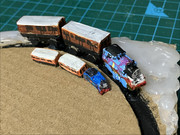
Size comparison. Don’t really like the new proportions and shades, but I didn’t have (or couldn’t find) a light blue that wasn’t mixed with white. They’re sized somewhere between the micro Plarail and Activity Island versions. Annie and Clarabel were painted just with markers (brown over orange for the main bodies).
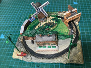
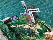
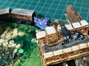
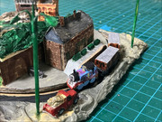
No progress photos were taken when I worked on this (besides the unpainted base), even though it took longer than I estimated. Because the intro only consists of three shots, it allowed me to divide the base into two halves - one for the windmill and bridge and the other for Ffarquhar - and link the locations in the order they appear in while adapting the straight track to the circle.
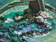
Most of the detail went into the windmill and lake portion since it’s the most overgrown. The shrubs are made of A4 and tissue paper strengthened with superglue, and my main glue was also used to add a gloss effect to the water. Hole punch pellets (HPP; both paper and cardboard) were used for the rocks and lily pads, the majority being unpainted (or partially painted) to exploit the natural shades of the cardboard. The sails are static and don’t turn as I felt there was no need for it.
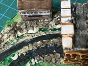
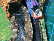
The signal box and the bridge. Like the rocks near the windmill, HPP were glued and clumped together to form ballast. Since it’s originally a double-track line and Thomas runs on the left (viewer’s right), I added a stretch of fake track next to the one that moves him; making sure it looked like the same “gauge”. The biker boy is just a 2D piece painted on the back with a paper strip for the arm that rests on the bridge, and his bike uses HPP for the wheels and extra bits for the frame, seat and handlebar.
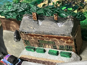
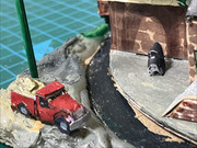
The Ffarquhar portion. Like in TOMY, the station building is (kind of) in the wrong main colour and
the platform is too short in length (mainly to prevent Thomas from fouling it when he gets there). More tissue paper was used for the treetops (bushes?) over the wall behind it, and the car and lorry were shaped the same way as the train. For the lamp posts, I simply pushed full toothpicks into the hot melt glue and added paper lamps at the tops.
Although it usually gets stuck when going under the bridge, the “track” still works like it did when I started building the base. Oddly, Clarabel had to be raised a bit higher than the other two since she kept breaking off (or just losing her wheels) between test runs. Very happy with how this “layout” turned out and would love to find how to make chain drives for more complex ones without buying LEGO tread links. Demos: windmill; bridge; Ffarquhar
Funny coincidence: the same day I nearly finished this layout, Ori Pfeffer wore this Thomas/“Crazy Train” (Ozzy Osbourne) shirt to his debut on Rokdim im Kokhavim (before and after his first dance).